- Article
- Related
What is flatness?
Flatness is a measure of a surface’s form that indicates whether all of the points along that surface lie in the same plane. Symbolized in Geometric Dimensioning and Tolerancing (GD&T) by a parallelogram, flatness is particularly useful when two surfaces must be assembled together to form a tight seal.
The flatness tolerance is determined to ensure that a given surface is located within two imaginary, perfect, and parallel planes. In other words, the tolerance zone is between the highest and lowest acceptable points across the plane of the surface being measured.
The flatness tolerance is determined to ensure that a given surface is located within two imaginary, perfect, and parallel planes. In other words, the tolerance zone is between the highest and lowest acceptable points across the plane of the surface being measured.
How to measure flatness
Measuring flatness consists of analyzing a surface to find how it is not perfectly flat. To do so, the first step is to acquire points on the surface that will allow you to find an envelope of two parallel planes that include all of these points. The next step is finding the smallest possible sandwich of planes, regardless of the orientation (as these planes can move freely in space). The distance between the two furthest points corresponds to the flatness. Therefore, the narrower the space between these two planes, the flatter the plane is.
What are the different testing methods for measuring flatness?
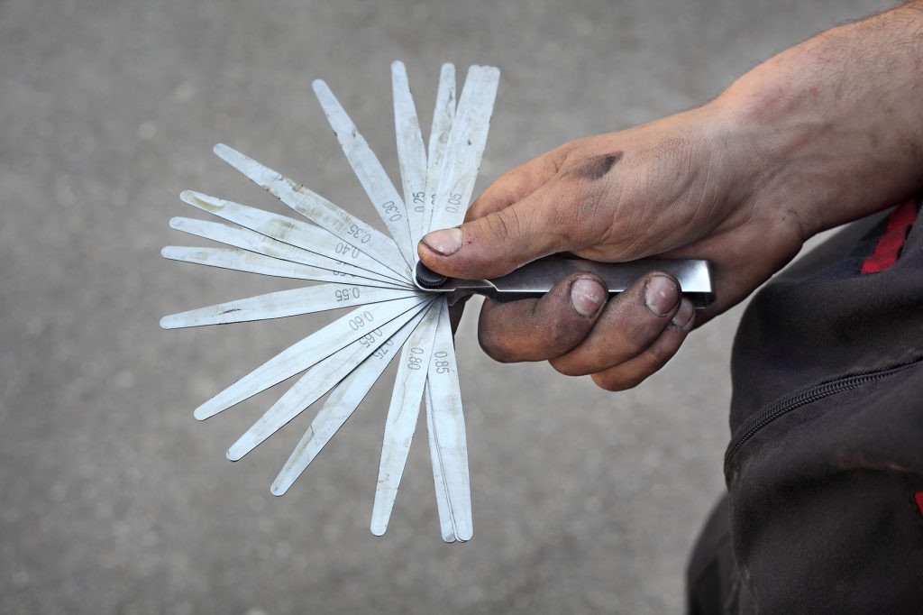
The feeler gauge and the height gauge are two traditional measurement tools; they certainly have a cost advantage and higher ease of use, but the accuracy of their measurements depends strongly on the user’s manipulations, the setup, and the environment where the measurements take place.
The first method for testing a part’s flatness consists of laying the part on a CMM marble with a pre-defined flatness. Then, using a feeler gauge, which is made of strips with already characterized thicknesses, we try to insert strips of different thicknesses under the part. Since we know that a surface, once positioned on the marble, will rest iso-statically on its three highest points, we then have the capability to find its flatness.
The first method for testing a part’s flatness consists of laying the part on a CMM marble with a pre-defined flatness. Then, using a feeler gauge, which is made of strips with already characterized thicknesses, we try to insert strips of different thicknesses under the part. Since we know that a surface, once positioned on the marble, will rest iso-statically on its three highest points, we then have the capability to find its flatness.
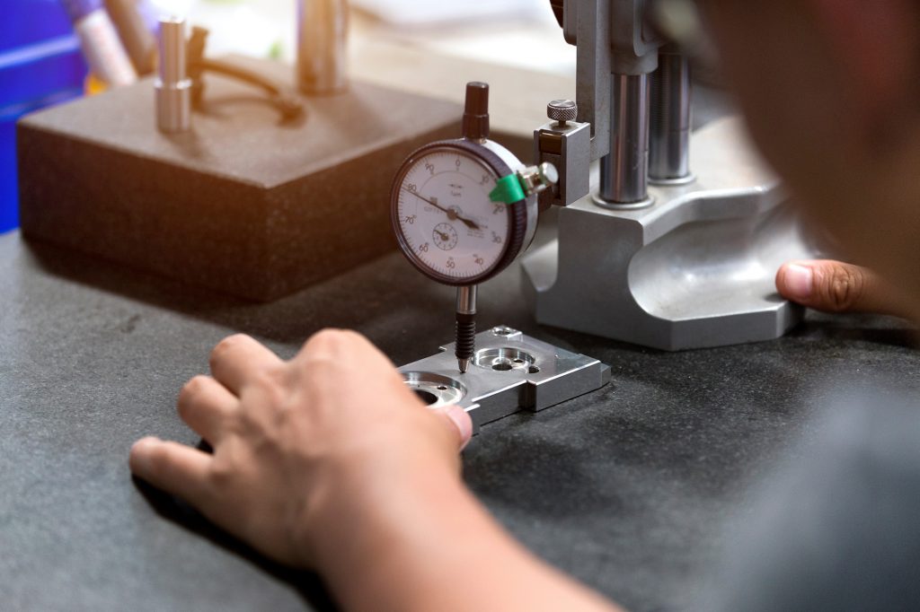
The same measurement method is possible with a height gauge that has a dial indicator holder. Once the part has been laid on the marble, it is possible to determine its flatness by moving the ruby over the surface, determining the maximum and minimum points. As previously explained, this envelope corresponds to the surface’s flatness.
The advantage of these two instruments is that they cost almost nothing beyond the price of the traditional tool itself, which is generally very affordable. However, the disadvantage of this approach is that the maximum and minimum values found depend on where the user has moved the gauge on the surface; if the gauge has not passed through the points corresponding to the actual highest and lowest points on the part, the flatness found will be erroneous. Moreover, these two methods can measure flatness in accessible areas only. For example, measuring a 4ft x 8ft plane on a CMM marble using a filler gauge would be possible only on the outline of the plane and not in the center because there is no filler gauge long enough to reach the middle of such a large surface.
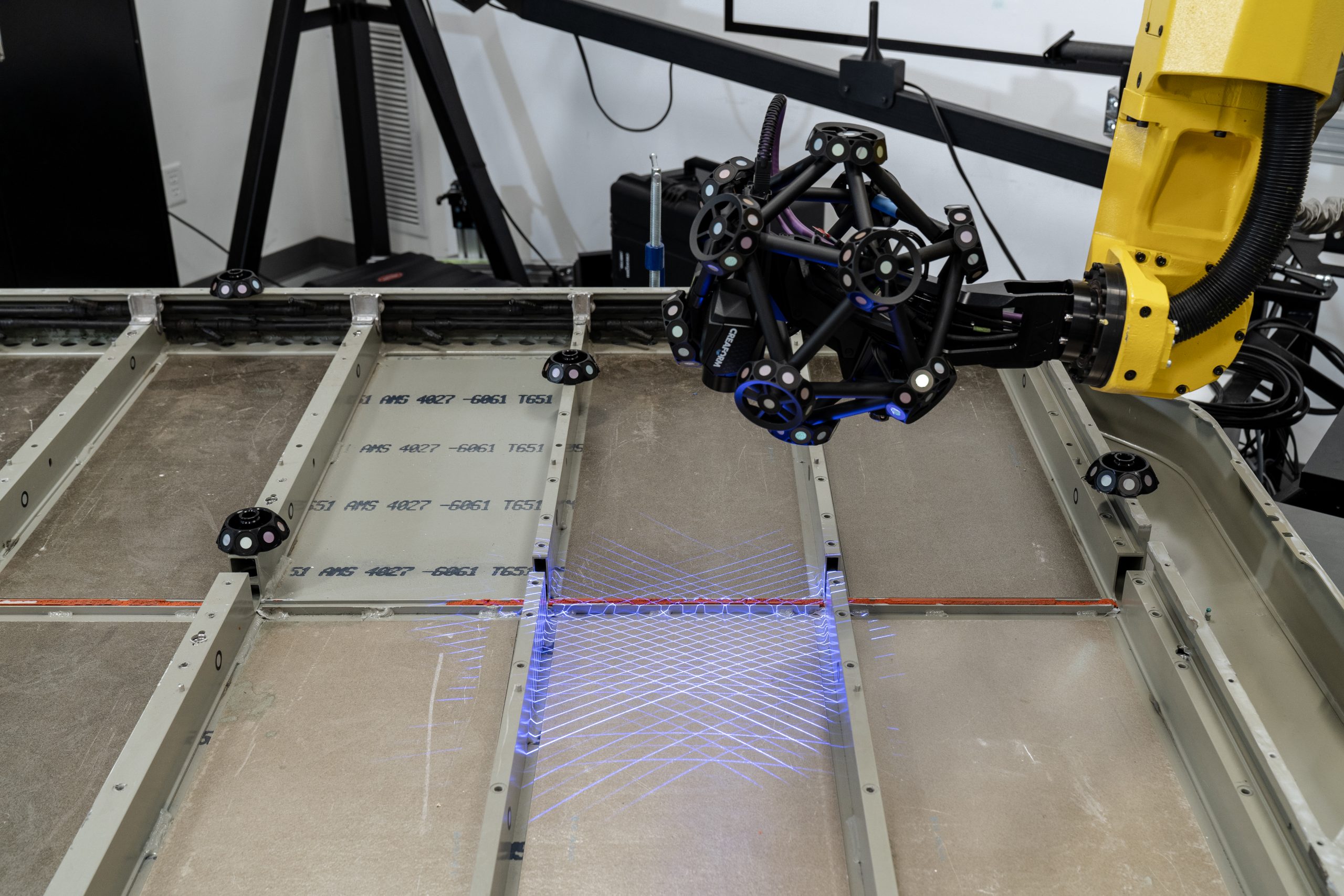
Among the other instruments for measuring the flatness are traditional CMMs, portable CMMs, and 3D laser scanners, but the same challenge arises with touch probes as with traditional instruments. Indeed, if the maximum and minimum values are misidentified, the analysis will be distorted. A 3D laser scanner, however, scans the entire surface and, thus, acquires a much higher density of points, resulting in an infinitely greater chance of measuring the highest and lowest possible points.
Among the other instruments for measuring the flatness are traditional CMMs, portable CMMs, and 3D laser scanners, but the same challenge arises with touch probes as with traditional instruments. Indeed, if the maximum and minimum values are misidentified, the analysis will be distorted. A 3D laser scanner, however, scans the entire surface and, thus, acquires a much higher density of points, resulting in an infinitely greater chance of measuring the highest and lowest possible points.
Why is flatness so important?
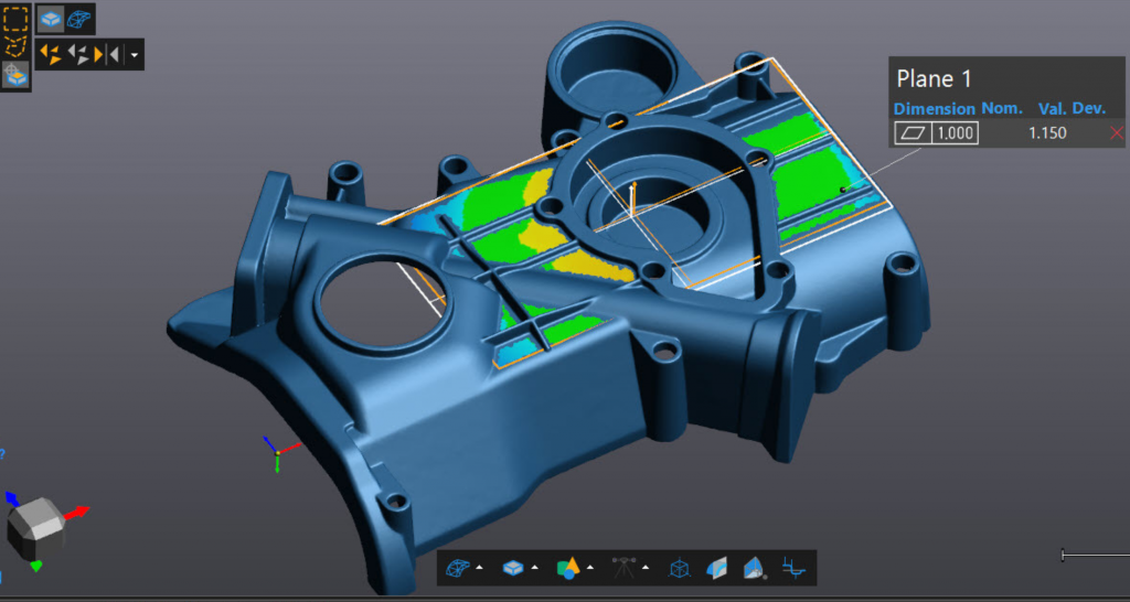
When we have a nominal model (a CAD) and a cloud of points acquired by 3D scanning, it becomes a matter of correlating the two by registering the scan data with the CAD model. To do this, we can use datums, which are reference entities. In metrology, the plane is an entity widely used to register measurement points with the CAD. Indeed, when a part must be analyzed to understand what is wrong in comparison to the CAD, metrology most commonly uses an alignment made of three planes.
So, once the plane-plane-plane alignment has been obtained, it is possible to perform a colormap to determine if the entities are in the right places and if the geometry is correct. If not, the machining program must be adjusted.
However, if the registration of the data with the CAD model is based on surfaces that are supposed to be flat but are not, we will end up in a situation where the entities are well machined except for the reference surfaces. In this case, an error message will indicate that all aspects of the part are wrong since the errors caused by the reference surfaces would be projected onto the entire part. This would lead one to believe that the part is badly manufactured and must be rejected, when it is just the datum and alignment entities that are badly machined. In this case, reworking one or two surfaces may help to save the part from scrap, which can be translated into huge money savings.
Therefore, when choosing planes as datums, it is always better to check their flatness first, as this will subtract major problems. This is valid for both the primary, secondary, and tertiary datums, which must all have good flatness and perpendicularity. It also guarantees that, if errors are found on the part, they will be machining errors and not projected errors on the alignment entities.
In short, while planes are probably the most popular geometric entities in all metrology alignments, if they are not machined correctly and have poor flatness, then all other geometric entities will also be incorrectly positioned.
When should flatness be measured?
Flatness measurement can be performed in quality control to inspect defined geometric entities or prototypes to understand what is wrong with a part. However, it is possible that, during the first stages of prototyping, there will be bigger problems to solve than flatness. A best-fit surface to control the shape and a first colormap to identify major problems could be enough for controlling the prototype. After all, at this early stage of development, we are mainly looking at the general shape of the part and ensuring that everything is generally right.
It is only after these early prototyping stages are completed that we can determine which bearing surfaces will become a primary datum. This will be followed by an alignment and a second colormap to check the positioning of the surfaces relative to each other. The data collected and analyzed during the second colormap will also be important during quality control because it will provide engineers with interesting information on whether the part is assembled with the other parts correctly.
When two parts are assembled together, it is important to choose the right reference surfaces. Generally, we choose surfaces that will be in physical contact via support points. In the specific case of support planes, it becomes crucial to control their flatness because the repeatability of the manufacturing process will depend on the flatness of these support planes. Thus, irregularities appearing on the colormap are a red flag that real errors must be corrected—not projected errors, as detailed above. Changing the tooling and redoing the machining program will then be necessary and justified.
The worst thing that can happen is modifying a piece of tooling when the identified problem was only an alignment error on an entity that was not planar; in this particular case, we regret not having measured the flatness. Therefore, it is important to measure flatness correctly, because decisions made on alignment entities can have costly consequences.
Consequently, measuring flatness is important for support surfaces that play major structural roles within the part. However, if the surface is only aesthetic and will be hidden later by a piece of plastic, the flatness calculation is, in this context, less relevant. The importance depends on the application, the functional character of each of the surfaces, and the role that the part will play in the final assembly.


Article written by Creaform
Published 11/01/2022
Published 11/01/2022
Recent Posts
Filters
Reset