


July 24, 2024
Improving Vessel Integrity at a Refinery thanks to Advanced 3D Scanning Technology See the article- 1 How to guarantee that manufactured parts correspond to the production requirements?
- 2 QC challenges: Non-predictable phenomena
- 3 Solution: An iterative inspection process
- 4 Conclusion: How 3D scanning mitigates quality control issues
How to guarantee that manufactured parts correspond to the production requirements?
At the beginning of a manufacturing process, a mold, die, or jig is engineered according to the theoretical CAD model. The aim of this tooling, made precisely from the nominal model, is to produce parts that correspond to the technical requirements.
It turns out, however, that there are often differences between the theoretical model and the reality of an industrial environment. Different phenomena interfere with the tooling, causing problems and imperfections on the parts.
Adjustments and iterations are required to ensure that the tools and molds, even if they correspond exactly to their nominal models, produce good parts that meet quality controls and customer demands. These adjustments and iterations can be simplified and accelerated thanks to 3D scanning and 3D scanning inspections.
QC challenges: Non-predictable phenomena
The reality of an industrial environment differs from the theory illustrated in CAD models. During the manufacturing process, several phenomena that are difficult to predict can occur. Spring backs when stamping a die, shrinkage when building a mold made of composite material, or thermal forces when welding two elements together are all good examples of phenomena that impact tooling precision. Nevertheless, modeling the removal of a composite resin, the spring back of a die, the impact of a weld remains difficult, complex, and expensive.
Initially, the tooling is built according to the theoretical model, which is developed to create manufactured parts that meet the production requirements. But, in the reality of the industry, the aforementioned phenomena interfere with the molded or stamped parts. As a result, the parts do not meet the technical demands and must be adjusted, corrected, and altered in order to pass the quality controls.
Starting with nominal models is, of course, a good first step, but let’s not forget that what manufacturers want is not so much a perfect tooling, but good parts that meet technical requirements and customer needs.
Solution: An iterative inspection process
The most commonly used method is to work on the part before adjusting the tooling. More precisely, this method involves producing a part, measuring it, and analyzing deviations between the part and the CAD model. Hence, if we notice that there are some missing (or extra) mms in one place, we will go to the corresponding surface on the mold, die, or jig in order to grind or add material. Thus, the iteration is performed on the tooling after measuring the manufactured part.
Once this operation is completed, we restart the manufacturing process in order to produce a new part that will be measured to verify if there are any remaining deviations. This iterative process will continue on a loop until we obtain the desired part (i.e., when the manufactured part corresponds to its CAD model).
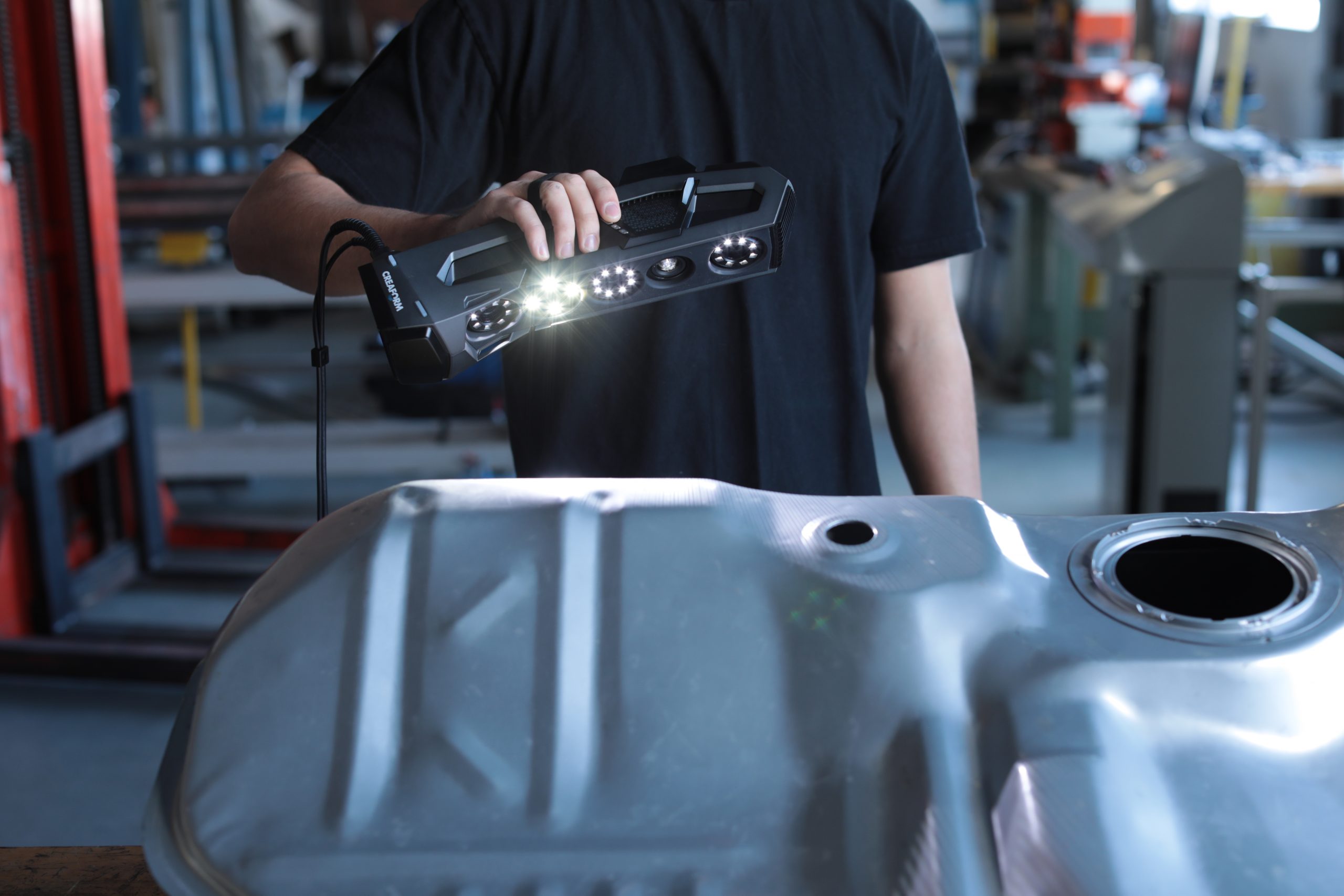
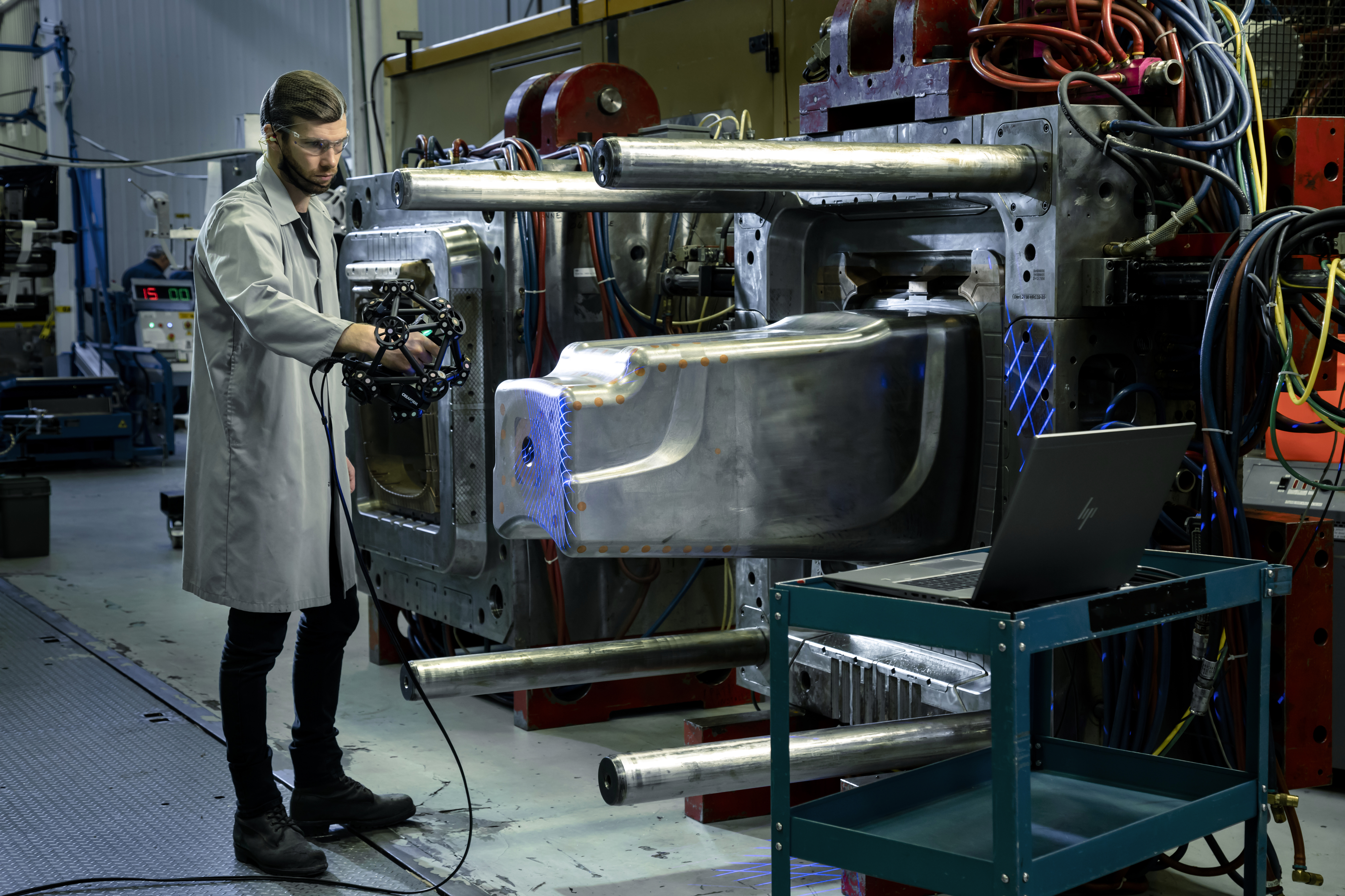
This iterative process of quality control requires a fast measuring tool in order to produce the next part without delay. In addition, the measurement technology must have the capability to be used directly on the shop floor and the capacity to measure all types of sizes, surface finishes, and geometries. 3D scanning technology, with its speed, portability, and versatility, enables production teams to make the required corrections to the tooling quickly and effectively.
Benefits for manufacturing companies: CMM reports
The customer who buys the manufactured parts may require a CMM report from the tooling manufacturers. Thus, a second measurement tool that will reduce the CMM workflow is an important benefit for manufacturing companies. With a portable 3D scanner, they can measure the majority of the entities and multiply the intermediate inspections, preserving the CMM for the final inspection and report generation.
Benefit: Using reverse engineering for 3D modelling and digital archiving
Once we have a tooling that produces a certified part, the mold, die or jig can be scanned as part of the reverse engineering process to create a 3D model. All initial iterations then can be saved for future productions. This means that if the tooling wears out and a new one is required, manufacturing teams can scan work directly from the model to build quality parts.
Thus, if the tooling wears out and a new one is required, we will not use the nominal model for the next manufacturing process. Instead, we can work directly from the model that we know builds good parts. All initial iteration time is saved for future productions.
Using 3D scanning for the reverse engineering of certified parts
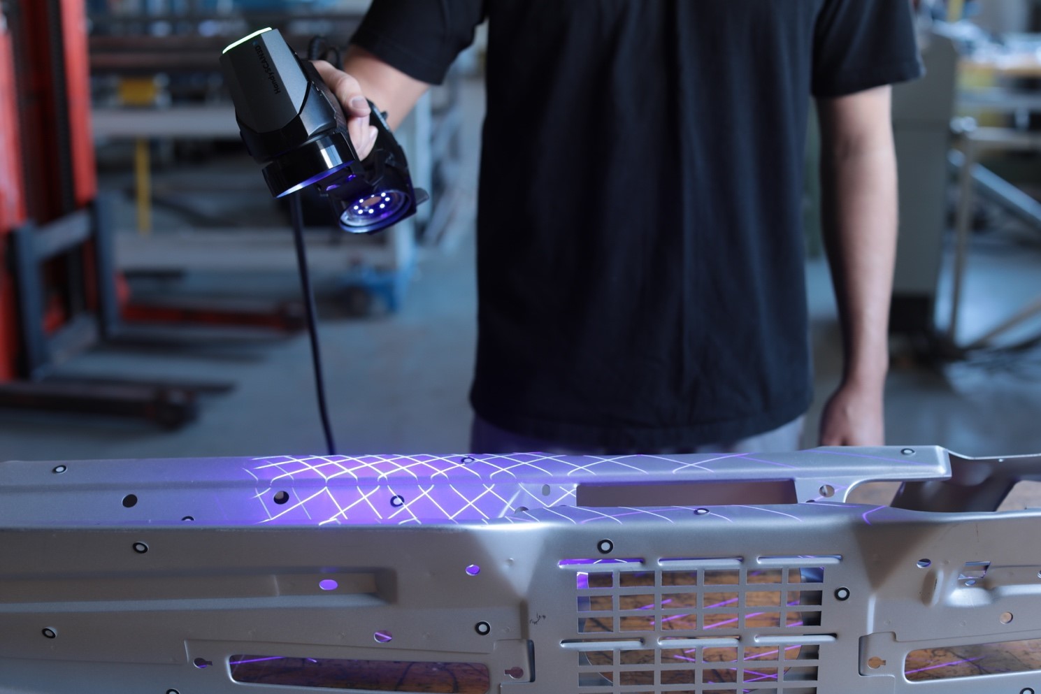
To reverse engineer a mold, die or jig, a 3D scanner is used. Depending on the application and scanning environment, one type of 3D scanner may be preferred over another. For example, a portable 3D scanner may be used to acquire the 3D measurements of a mold right on the production floor.
Once the measurements are taken, a post-treatment process must be carried out to finalize and prepare the 3D scan data to be used in a CAD software. This post-treatment process, which involves segmentation, alignment, and positioning the part in space,, is normally done using specialized software, such as VXelements. The result is a “clean” STL file.
Reverse engineering the 3D model
Once the STL file is ready, it can then be exported directly to CAD software, like SolidWorks, AutoCAD or Inventor, or into reverse engineering software and then CAD software.
A reverse engineering expert or industrial designer will remodel the part either “as is,” which means with potential imperfections, or based on the original design intent (parametric reverse engineering). Modifications can also be made to the 3D model, depending on the application or need.
Reverse engineering and 3D printing
Once the 3D model has been generated and improved upon, if required, many reverse engineering teams produce a prototype using additive manufacturing techniques.
The watertight CAD file is sent to a 3D printer for the prototype to be made. Experts can then assess if the 3D model is accurate or if additional changes and prototypes are required. Once the final 3D model is approved, it is sent for official tooling.
Benefit: Periodic quality control
Instead of measuring a part out of 50 or 100 with the CMM, 3D scanning technology enables the possibility of conducting periodic quality controls. Indeed, a portable 3D scanner is beneficial for the mold and tool industry because it increases inspection sampling and saves time by measuring parts directly on the floor of production without having to bring them to the CMM. Thus, periodic quality controls ensure that the production remains in control and delivers parts on time.
Benefit: Quality assurance
If the manufactured parts suddenly do not match the technical requirements, the manufacturing company will fall into an investigation mode, which will cause a lot of stress and uncertainty. With a portable 3D scanner, quality assurance will be able to intervene without further delays and find the root cause by acquiring a lot of data quickly and investigating directly on the shop floor.
Conclusion: How 3D scanning mitigates quality control issues
Several phenomena specific to an industrial environment regularly occur on the production floor. They cause unexpected spring backs or shrinkage. Necessary adjustments are required to ensure that the tooling, even if it exactly matches its nominal model, produces good parts that meet quality controls and customer requirements. These iterations are facilitated by 3D scanning, which, due to its speed, portability, and versatility, is an effective alternative to the CMM that can remain free for final inspections. In addition, 3D scanning offers the possibility of reverse engineering the tooling that produces the good parts, performing periodic quality controls, and quickly resolving unexpected issues that may occur at any time.