Since the last release of Pipecheck (Version 3.1), it is now possible to manually define a feature’s area in order to generate a specific analysis for the latter.
The goals of this operation are to either (1) investigate more on a defined area, (2) validate the partial areas that need to be repaired or (3) to facilitate the correlation with the ILI data.
Investigate more on a defined area
If needed, the inspector can isolate individual corrosion pits to perform a separate ASME B31G analysis in addition to the one performed on the overall surface in respect to the interaction rules.
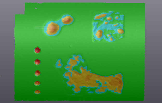
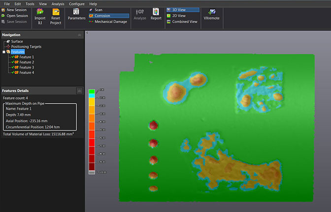
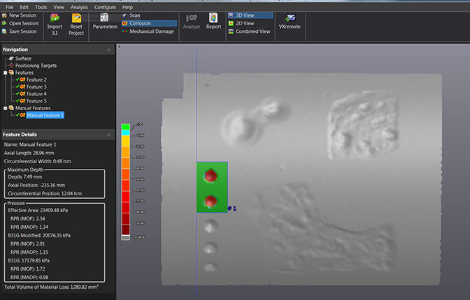
In this example, the analysis has resulted in four features.
However, one can be interested in the specific results for every single, or some of, the ‘pin holes’ grouped together, which located on the left side.
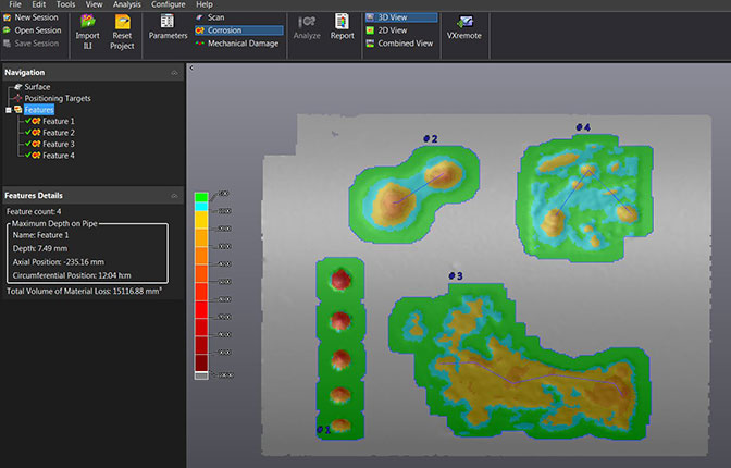
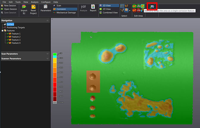
In the SCAN branch of the navigation tree, the user can select an area and use the NEW feature to manually ‘assign the area as a single corrosion feature’.
After having run the analysis, the result is a new feature defined by the user’s selection located under the new ‘ Manual Features’ node in the tree. This feature has its own results, which are independent from the other neighboring pits and features.
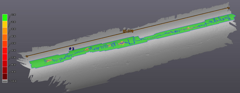
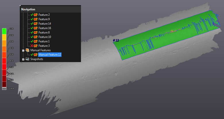
Validate the Partial Areas that Need to Be Repaired
Using the same tool, an inspector can find out if a partial repair could be enough to make the pipe ‘fit for service’ again. From the first global analysis, one can define a smaller area as Manual Feature, specifying the remaining ‘unrepaired’ feature. If the results of this Manual Feature are satisfactory for the ‘fit to service’ criterion, then the partial repair of the original feature’s other area is feasible.
Facilitate the Correlation with the ILI Data
In some cases, the size or the interaction rules applied to the features by the ILI can differ from the Pipecheck’s analysis. In such cases, the matched of these features done by Pipecheck in order to correlate the results could be misleading.
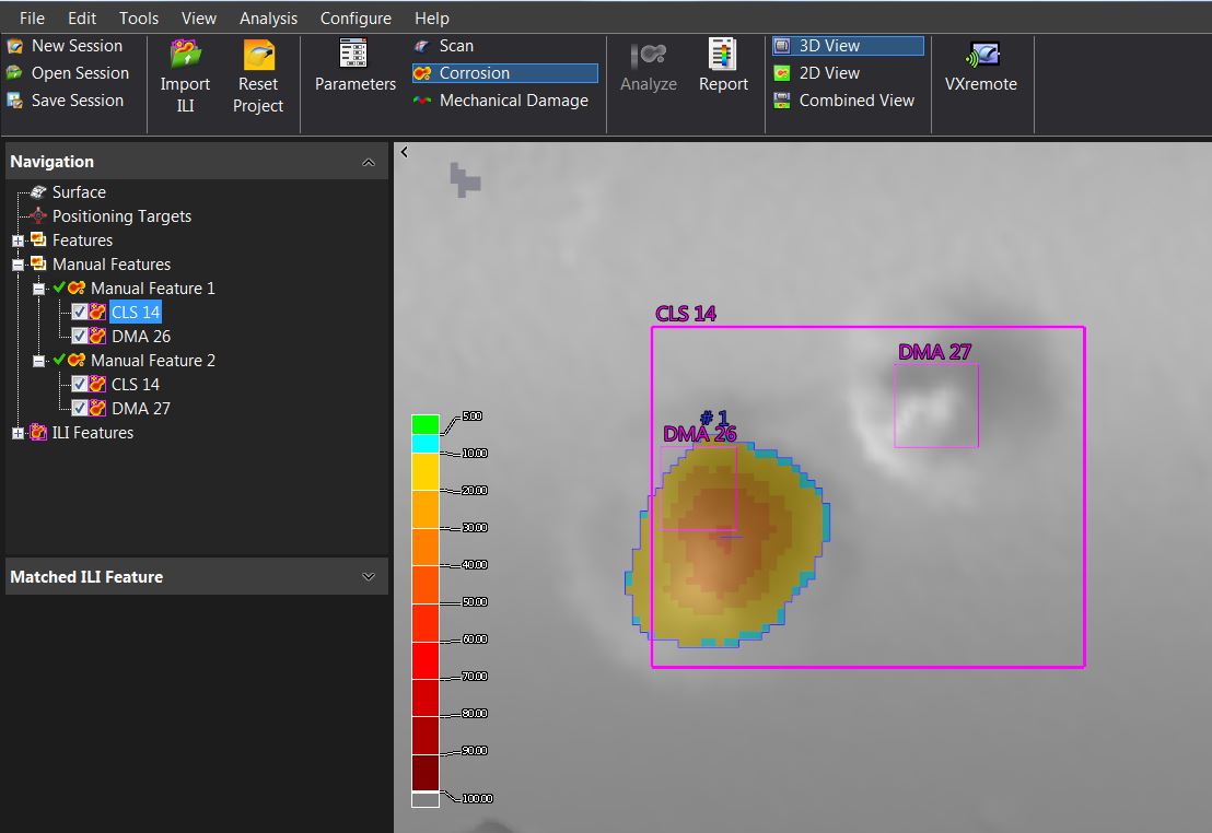
In the following example, both DMAs and Clusters were exported by the ILI smart tool . As all three overlap the sole Feature 2, they will all be compared to the latter, which would cause a correlation error as the size of the DMA26’s pit and the DMA27’s pit will be compared with the Feature’s size.
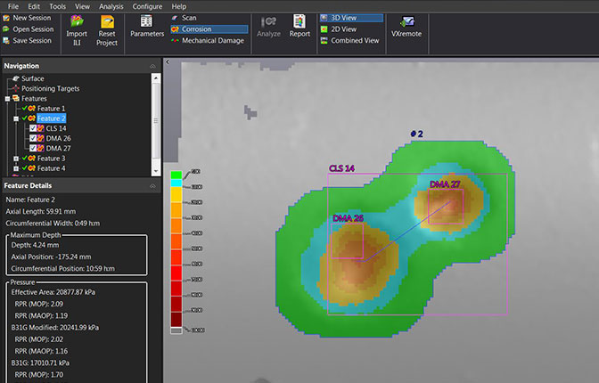
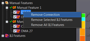
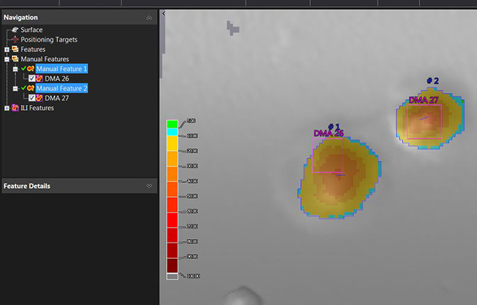
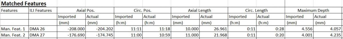
Once manually defined, both pit’s area can now be compared with the DMAs. As the CLS 14 also overlaps the manually defined features, it will also first be associated. However, its connections can be manually removed, if needed, leaving only the associated DMAs.